


Rated short-circuit breaking capacity
Rated short-circuit breaking capacity represents the highest value of short-circuit current that a circuit breaker or fuse is capable of interrupting. Each protective device is designed for a specific rated power and therefore for a specific rated (load) current. Short-circuit currents can permanently damage protective devices due to excessive heat and the energy released. In electrical power engineering, we use various types of electrical equipment (protective devices) with different technical specifications that also describe short-circuit capacity. Let us look at some examples.
Examples of Protective Devices
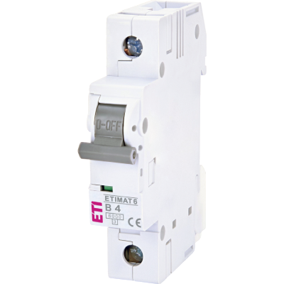
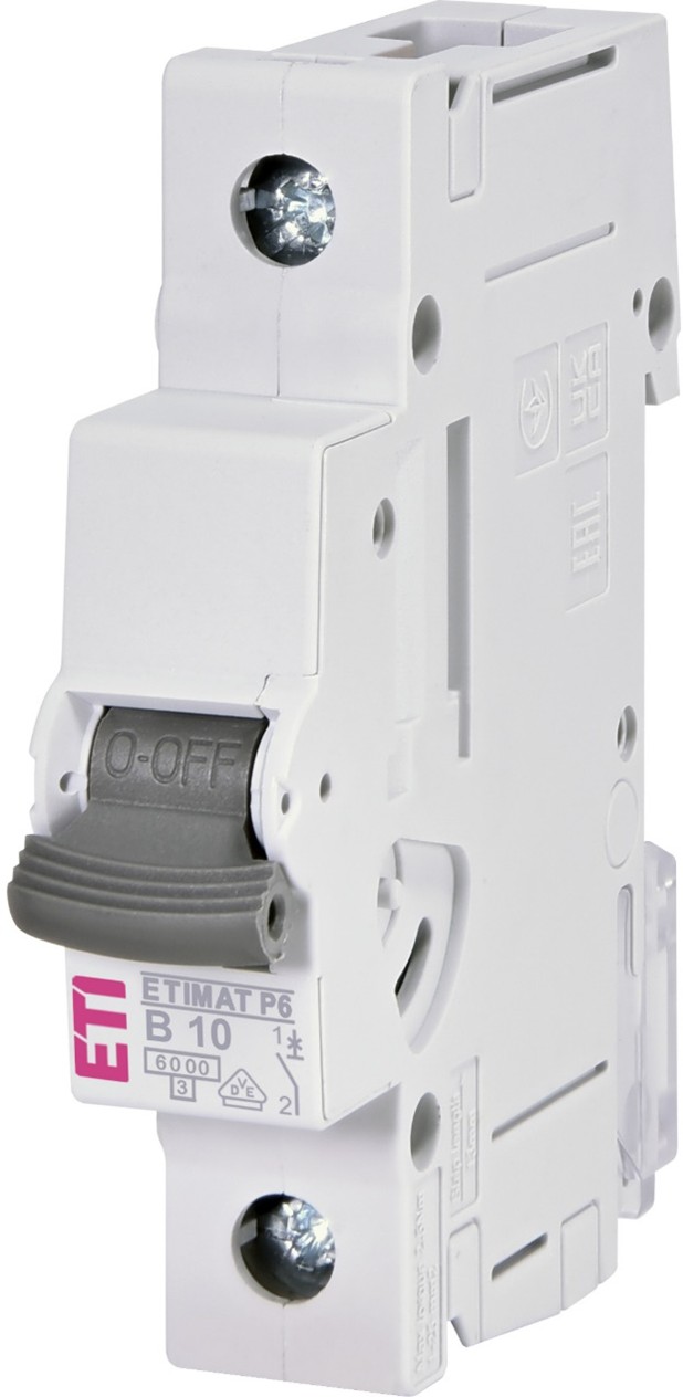
Picture 1 shows a miniature circuit breaker with a rated short-circuit capacity of 6 kA.
A miniature circuit breaker (MCB) protects low-voltage electrical conductors and cables in the event of a short circuit or overload. The MCB includes various markings that describe its key characteristics: rated current In (in Picture 1, 10 A), tripping characteristic or time-current (I–t) curve (in this case type B, but also C, D, K, and Z exist), and short-circuit breaking capacity (in Picture 1, 6000 A), which will be discussed further below.
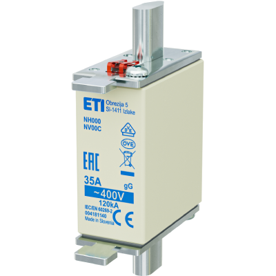
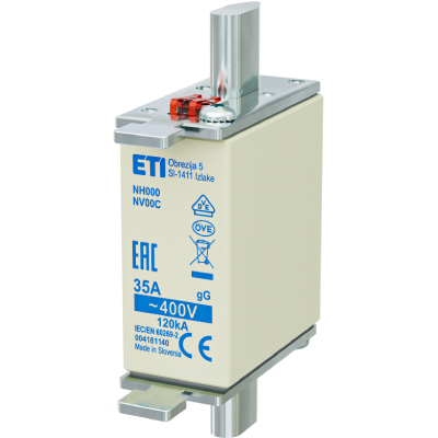
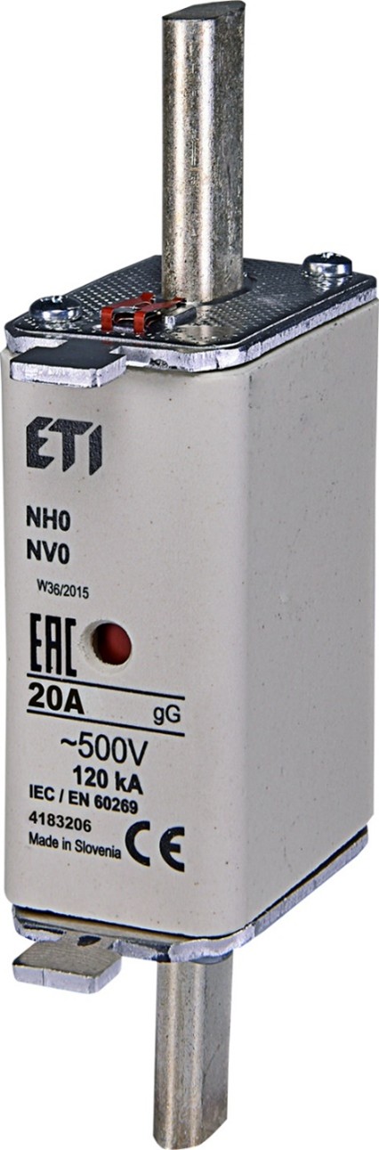
Picture 2 shows a fuse-link, which also protects low-voltage conductors and cables in the event of a short circuit or overload. The fuse link contains markings that describe important characteristics: rated current In (20 A), rated voltage Un (500 V), time-current characteristic (in this case gG, where “G” means general-purpose use), and rated short-circuit breaking capacity (120 kA).
Picture 3 shows a low-voltage molded case circuit breaker (MCCB), which also protects low-voltage conductors and cables in the event of a short circuit or overload. The breaker includes various markings: rated current In (32 A), rated operational voltage Ue, rated insulation voltage Ui (in this case 800 V), rated impulse withstand voltage Uimp (in this case 8 kV). With a screwdriver, the short-circuit protection can be adjusted, as well as the rated current Ir, thereby changing overload protection. The breaker also indicates the selectivity category (in this case A, but it can also be B).
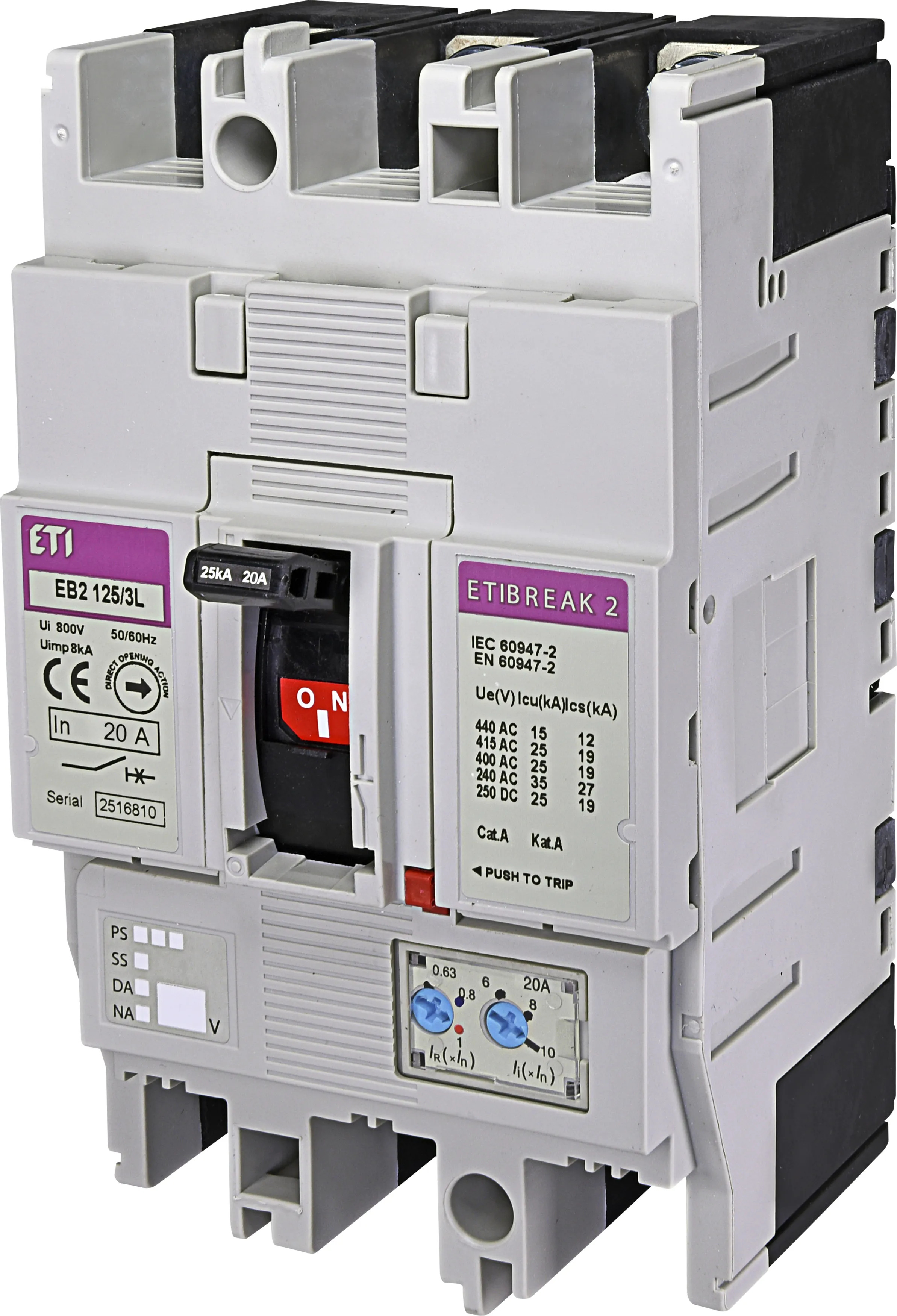
For the purpose of this text, we will focus on short-circuit capacity, indicated by the following markings:
Ue = 440 V, Icu = 25 kA, Ics = 25 kA. What do these mean?
Rated Ultimate Short-Circuit Breaking Capacity (Icu)
The rated ultimate short-circuit breaking capacity (Icu) is the maximum value of short-circuit current that a circuit breaker can interrupt.
It must be higher than the maximum possible short-circuit current in the network, which is typically a three-phase short circuit.
In our example (at 440 V): Icu = 25 kA.
This means that after the test sequence (switch on – short circuit – switch off), the breaker must remain undamaged and must still provide basic overload protection.
Rated Service Short-Circuit Breaking Capacity (Ics)
Since Icu represents an extreme condition that is less likely to occur, manufacturers also specify the current Ics according to standards.
We want the circuit breaker to interrupt short-circuit currents that occur more frequently in the network in such a way that it remains in good condition even after one or several interruptions.
Therefore, Ics was introduced and is expressed as a percentage of Icu.
Most molded case circuit breakers often have Ics = 100% of Icu, which in our example means 25 kA (at 440 V).
After the test sequence (switch on – short circuit – switch off – pause – switch on – short circuit – switch off), the breaker must remain undamaged even after three interruptions at the expected short-circuit current. After this test, the device must still provide basic overload protection.
How Large Can Short-Circuit Currents Be?
To determine short-circuit currents, we must know the impedance of the short-circuit loop.
Today, designers use computer tools to calculate the expected loop impedance at any point in an electrical installation (or network), which allows them to determine expected short-circuit currents.
Inspectors can also measure loop impedance and expected short-circuit currents using specialized instruments after installation or during maintenance.
Factors Influencing Short-Circuit Current
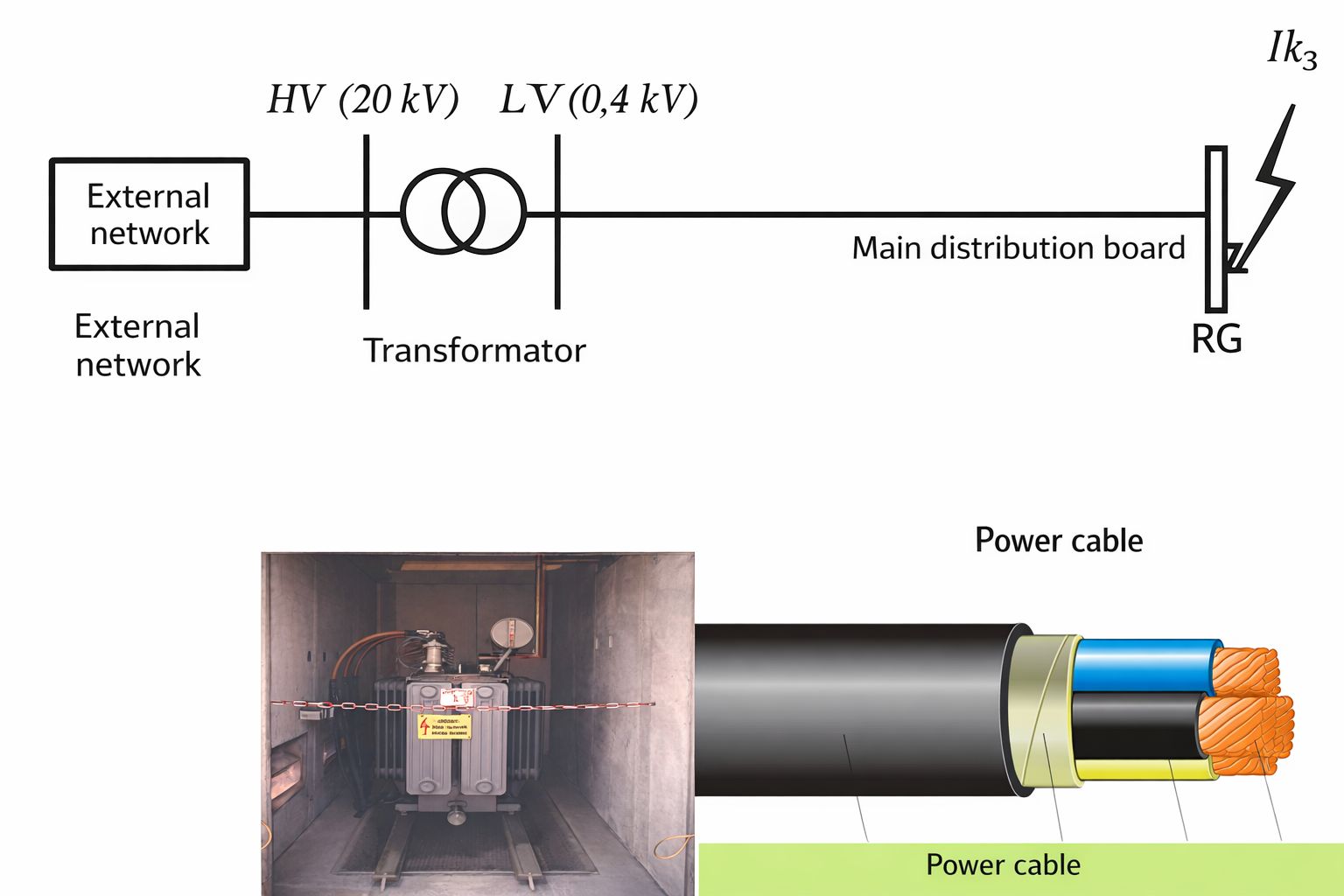
The following factors are very important for determining the magnitude of short-circuit current in low-voltage networks:
- The supply transformer, with its inductive and resistive components (short-circuit voltage and rated power)
- The impedance (resistance and reactance) of cables and conductors
- The impedance of the high-voltage network
Impedance of the Network
The total resistance up to the fault location is:
R = Rtrf + Rk
The total reactance up to the fault location is:
X = Xtrf + Xk
Where:
- Xtrf – transformer reactance
- Xk – cable reactance
- Rtrf – transformer resistance
- Rk – cable resistance
The impedance of the low-voltage network is therefore equal to:

Short-Circuit Current Calculation
The initial symmetrical three-phase short-circuit current is calculated using:

For a single-phase short circuit, the impedance is higher because the neutral conductor must also be considered.
Where:

- U – line voltage
- Uf – phase voltage
- Z – impedance of the short-circuit loop
If the protective device is installed in a distribution board, the short-circuit current will be significantly lower due to increased impedance caused by cable resistance. The closer the installation is to the transformer, the higher the short-circuit current. Three-phase short-circuit currents are also higher than single-phase currents.
Conclusion
We must always consider whether it is better to use a cheaper switching device with lower short-circuit capacity or a more expensive one with higher capacity.
In many cases, the more expensive option is necessary, as the short-circuit breaking capacity must always be higher than the expected short-circuit current (Icu > Ik).
Additionally, a higher-rated device can improve part of the electrical installation by extending the service life of the equipment.