


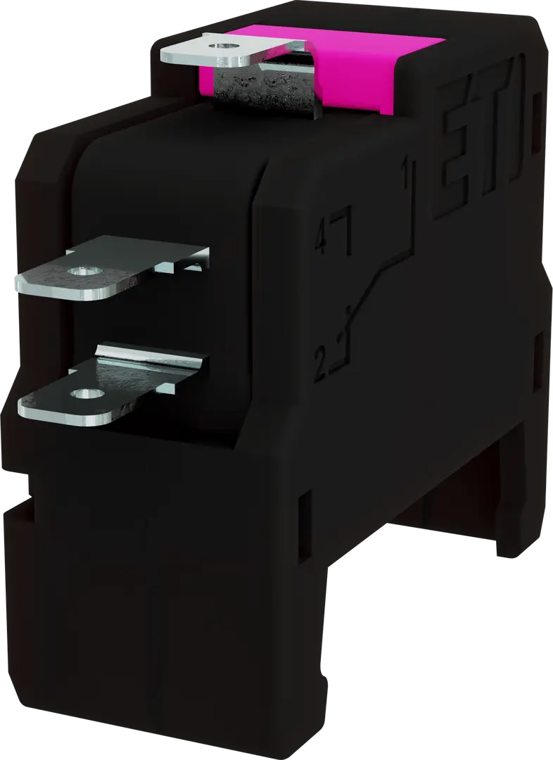
Electrodynamic Forces in RCCBs: How it Withstands Extreme Fault Conditions
During a short circuit, a residual current circuit breaker (RCCB) can experience forces strong enough to bend metal. These electrodynamic forces act within milliseconds, placing enormous mechanical stress on conductors, contacts, and structural components. Understanding how these forces arise—and how modern RCCB designs mitigate them—is essential for ensuring long-term reliability and electrical safety.
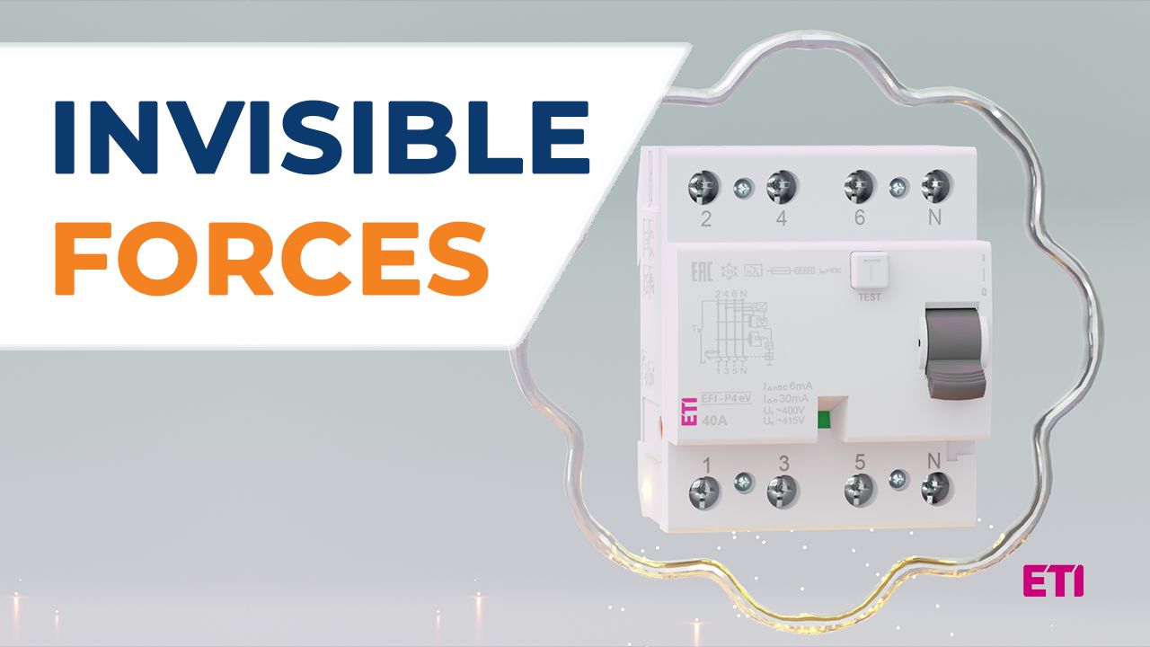
Residual Current Circuit Breakers (RCCBs) are designed to disconnect fault currents rapidly, preventing electric shock and fire hazards. While their primary function is detecting residual currents, the internal mechanical and electromagnetic stresses during high fault conditions are often overlooked. In extreme cases, short-circuit currents can generate electrodynamic forces capable of deforming conductive elements and stressing internal assemblies.
This blog explores the physics behind these forces and explains how ETI’s EFI RCCBs are engineered to withstand them.
Introduction
Whenever a high current flows through a conductor, it produces a magnetic field. Under normal operating conditions, these fields are moderate and manageable. However, during a short circuit, current can increase thousands of times beyond nominal values. The resulting magnetic interaction generates powerful electrodynamic forces inside the RCCB.
These forces act on current paths, mechanical supports, and contact systems. Without proper design considerations, they can lead to deformation, misalignment, and reduced switching reliability.
What Are Electrodynamic Forces?
Electrodynamic forces arise from the interaction between electric currents and magnetic fields. The phenomenon is governed by fundamental electromagnetic principles, including the Lorentz force and the Biot–Savart law.
In simplified terms:
- The higher the current, the stronger the magnetic field.
- The closer the conductors, the greater the interaction force.
- Opposite current directions create repelling forces.
Inside an RCCB, current paths are compact and precisely arranged. During a fault, magnetic forces between adjacent conductors can push them apart with significant mechanical intensity.
Electrodynamic Forces During a Short Circuit
When a short circuit occurs, the current surge produces intense magnetic fields within milliseconds. These fields generate internal forces that act on:
- current-carrying conductors
- contact assemblies
- insulating supports
- mechanical fastening elements
The consequences can include:
- Conductor deformation – bending or displacement of internal current paths.
- Contact misalignment – affecting arc extinction and switching precision.
- Mechanical stress on supports – increasing the risk of insulation damage.
- Arc formation or contact welding – due to improper alignment under load.
In extreme conditions, the forces generated can be strong enough to physically move metallic components. If not properly controlled, this may compromise device integrity.
Engineering Solutions in ETI’s EFI RCCBs
ETI’s EFI RCCBs are engineered with these forces in mind. Their internal structure is designed to resist mechanical displacement while maintaining precise switching performance.
1. Precision-Engineered Current Paths
The geometry and cross-sectional dimensions of current paths are carefully calculated to withstand high prospective short-circuit currents. Proper conductor sizing reduces excessive heating and limits mechanical stress. ETI uses COMSOL Multiphysics tool to create and test product model variations, simulating the electrodynamic forces generated within the RCCB, as it provides the
necessary data to replicate real operating conditions.
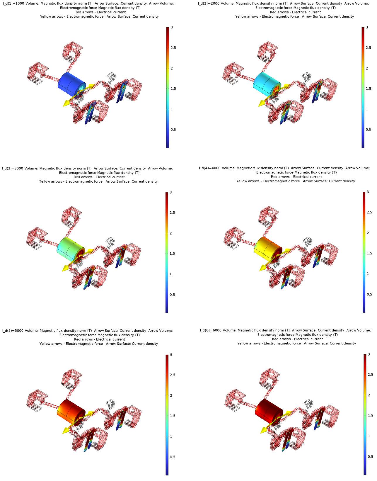
Example of a COMSOL Multiphysics tool simulation: Magnetic flux on ferromagnetic core, current density, and electrodynamic forces (yellow arrows) in the primary current path during short-circuit analyses for 1000 A, 2000 A, 3000 A, 4000 A, 5000 A, and 6000 A.
The short-circuit current values for each phase, prepared in such analysis, are then assigned to the corresponding RCCB current paths, mirroring the conditions of the actual short-circuit tests. The simulation results are analyzed to assess the magnitude and distribution of these electrodynamic forces in the RCCB. This analysis is essential for identifying and strengthening areas that may be prone to mechanical stress or displacement due to the forces generated.
Additionally, the optimized Ferranti transformer design ensures balanced magnetic interaction, minimizing asymmetrical force distribution within the device.
2. Finite Element Analysis (FEA)
Before physical production, ETI engineers simulate fault conditions using Finite Element Analysis (FEA). This modelling approach allows precise visualization of:
- magnetic field distribution
- mechanical stress points
- deformation risk areas
- thermal rise under load
By predicting stress behaviour during extreme current surges, engineers can refine conductor layout and support geometry before manufacturing begins.
3. Durable Materials for Mechanical and Thermal Resistance
Material selection plays a decisive role in reliability. EFI RCCBs incorporate:
- high-conductivity copper alloys
- mechanically reinforced contact systems
- heat-resistant insulation materials
- robust fastening structures
Each material is chosen based on its ability to resist mechanical deformation and thermal stress during fault conditions.
4. Tested and Proven Performance
Simulation alone is not sufficient. Every EFI RCCB undergoes extensive laboratory testing to verify mechanical strength and switching reliability under standardized fault scenarios.
Testing confirms:
- mechanical stability during short-circuit current exposure
- contact integrity after fault interruption
- consistent tripping performance
- compliance with IEC/EN standards
.jpg) Testing of RCCBs on our production line
Testing of RCCBs on our production line
5. Holistic Design for System-Wide Reliability
The interaction between electromagnetic forces and mechanical structures is analysed as a complete system. Components are not designed in isolation. Instead, ETI engineers evaluate how conductors, contacts, supports, and arc chambers perform together during extreme events.
This system-level approach ensures that even under intense electrodynamic stress, the RCCB maintains operational precision and protective function.
Practical Implications for Installers
For electricians and panel builders, mechanical robustness translates into:
- greater long-term reliability
- reduced risk of internal deformation
- stable operation after fault events
- confidence in protection performance
Choosing an RCCB designed to withstand electrodynamic forces means choosing predictable behaviour under critical conditions.
Conclusions and Recommendations
Electrodynamic forces inside RCCBs during short circuits are significant and unavoidable. Their impact depends entirely on engineering design, material selection, and structural stability.
ETI’s EFI RCCBs are developed with these forces as a core design consideration. Through optimized conductor geometry, FEA simulation, durable materials, and extensive testing, they maintain structural integrity and protection performance under extreme electrical stress.
Key Recommendations
- Select RCCBs tested for high short-circuit withstand capability to ensure mechanical durability.
- Verify compliance with IEC/EN standards for fault performance and structural integrity.
- Use high-quality devices in critical installations where reliability under fault conditions is essential.
Residual current circuit breakers are more than switching devices. They are engineered safety components designed to operate under extraordinary forces. With EFI RCCBs, ETI combines electromagnetic science, structural precision, and proven testing to deliver dependable protection for residential and industrial systems alike.